 Mars Rover Rocker-Bogie Differential
Today’s is a guest post, brought to you by my father, engineer, physicist, computer programmer, and Lego, Mars, and animation enthusiast: Keith Enevoldsen. If you’re not caught by the title of the post, scroll down and look at the pictures… then scroll back up and read the rest of the article because it is fascinating stuff! (P.S. He has a website full of awesome science stuff too!)
![]()
~ A l i c e !
The Rocker-Bogie
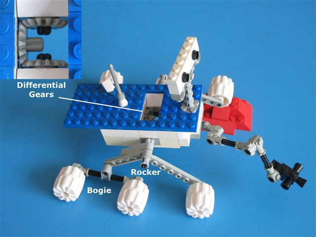
All the Mars rovers have six wheels and use a rocker-bogie suspension system to drive smoothly over bumpy ground. The rocker-bogies are easy to see in pictures of the rovers (see pictures below). There is one rocker-bogie assembly on each side of the rover. The rocker is the larger link that connects to the rover body (the chassis) in the middle (at the rocker pivot), has a wheel on the front, and connects to the bogie in the back. The bogie is the smaller link that connects to the rocker in the middle (at the bogie pivot), and has wheels at both ends. Each of the six wheels has its own motor.
The Differential
It is not so easy to see and understand how the rocker-bogie mechanism keeps the body level. What prevents the rover body from tipping all the way forward or backward around the rocker pivots? If you build a model rover and you attach the rockers to the body with an axle or two pivot pins, the body will tip forward or backward until it hits the ground! In the real rovers the two rockers connect to each other and to the body through a mechanism called a differential. The differential is what keeps the body level. Relative to the body, when one rocker goes up, the other rocker goes down. Relative to the ground, the body angle is halfway between the angles of the two rockers. That’s cool, but how does it work? The different rovers use different mechanisms: a differential gearbox or a differential bar.
Differential Gearbox
The Mars Pathfinder (Sojourner) and Mars Exploration Rovers (Spirit and Opportunity) use differential gearboxes.
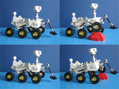
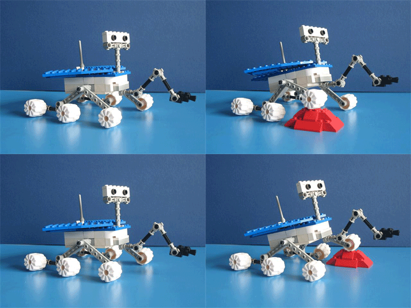
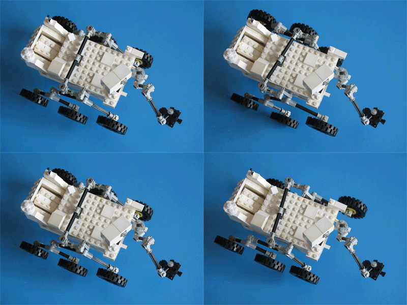
The gearbox is inside the rover body, so you never see it. No wonder it is hard to figure out how it works! In my Lego model rover shown here, I use a simple three-gear differential. Two gears connect to the two rockers and the third (middle) gear connects to the body. If you hold the model rover body steady in midair and tilt one rocker up, the gears will turn and the other rocker will tilt down (see the animations below).
The real Mars Exploration Rovers use more complicated gearboxes with more gears but they are functionally equivalent to this simple three-gear differential.
Differential Bar
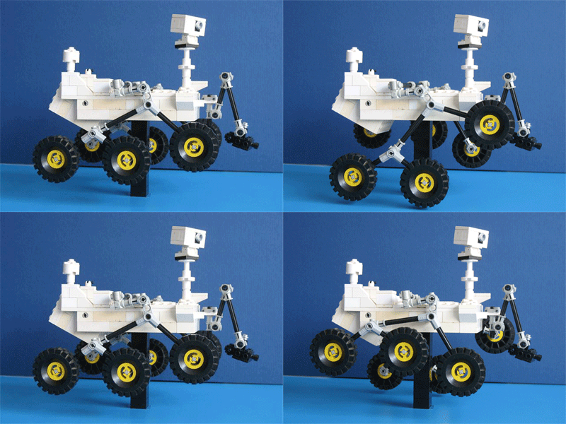
The Mars Science Laboratory (Curiosity) uses a differential bar. This is the big black bar that you see across the deck of the rover.
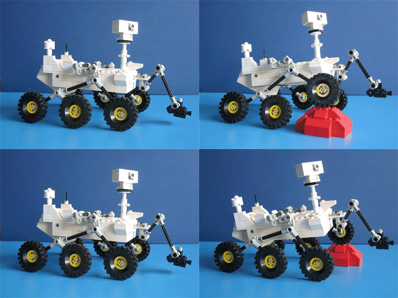
The middle of the bar is connected to the body with a pivot and the two ends are connected to the two rockers through some short links. If you hold the model rover body steady in midair and tilt one rocker up, one end of the bar will go back, the other end will go forward, and the other rocker will tilt down (see the animations below).
The Mars Exploration Rovers did not use a differential bar because it would interfere with the solar panels. But the Mars Science Laboratory does not have that problem because it is nuclear powered and has no solar panels.
Animations
Animations of a Rocker-Bogie with a Differential Gearbox
Mars Exploration Rover (Spirit and Opportunity)
Body held steady in midair:
Wheels on the ground:
Animations of a Rocker-Bogie with a Differential Bar
Mars Science Laboratory (Curiosity)
Body held steady in midair:
Wheels on the ground:
No Springs
The rocker-bogie mechanism has no springs. The absence of springs helps it keep all six wheels on the ground with approximately equal pressure on each wheel. This is a good thing when you are driving on sand!
Want More? (and References)
“Mars Exploration Rover Mobility Assembly Design, Test and Performance”, JPL
“A Capable and Temporary Test Facility on a Shoestring Budget: The MSL Touchdown Test Facility”, JPL
I hope you enjoyed my dad’s post. He sure had fun figuring out those mechanisms and creating them out of Lego!
I’ll be posting a Curiosity-landing-“watching” event here very soon.
![]()
~ A l i c e !






Another take from the internet:
http://www.flickr.com/photos/65402716@N07/sets/72157627997956311/with/7624731040/
Thanks Kevin!
I’d like to thank Emily Lakdawalla for her help. I had emailed her a photo of one of my earlier Lego rovers and said I knew something was missing from my rocker bogie mechanism, but I couldn’t figure out what. She supplied me with the key word “differential”.
Picture from surface:
http://home.comcast.net/~markp99/images/curiosity1.jpg
this made getting it so much easire! thank you
Actually your differential does not look so “simplified”!
http://library.iyte.edu.tr/tezler/master/makinamuh/t000341.pdf
Thanks for gathering this information, LEGO is a great way to show how the suspension works!
You mention that Sojourner used a differential gearbox but it looks to me like it used a differential bar, see this image: http://er.jsc.nasa.gov/seh/marspathrov.jpg
The only mention of the differential I’ve found for Sojourner is in this text (http://www.mit.edu/~ykuroda/research/iSAIRAS99-M5SUS.pdf) where they suggest it used a differential bar.
The image you sent shows the rocker-bogie system, but not the differential. The link you send is for MER (Opprtunity and Spirit), Sojourner was before that. I still think that Sojourner had a gearbox — but my research was a LONG time ago.
In the picture if you look at the front of the rover there is a bar with a pivot in the centre just underneath the solar panel. This bar then extends around both sides of the rover and connects to an arm protruding from the top of the rotary joint where the rocker attaches to the body of the rover. This looks a lot like a differential arm to me but perhaps that’s not the actual flight model Sojourner…?
In the PDF I linked to, under section 3.3 it states:
“Rocker-bogie suspension [2]-[4][12][13] is the
system to rove on Martian surface in the mission
Mars Pathfinder”
which is of course the mission to which Sojourner belongs. It then states:
“A pair of lockers and the
body are connected via a differential bar in order to
stay pitching angle of the body at the middle of two
lockers”
However that text is about “Micro5” (not MER?) and, while I’ve read most of their references, I can’t find any other mention of Sojourners differential.
Hmm..
Okay, this is going to sound a bit like a cop-out, but let me get my dad to take a look at it, since he’s the one who built the LEGO models and did the research for this post.
I see the bar you’re talking about, but I’m not yet convinced that it is the differential. I should find some citations myself, eh?
Are you in agreement that MER used a differential gearbox or not that either?
Hang on, let’s see what Keith says.
-Alice
Pluto is correct and I was incorrect. The Pathfinder rover photo http://er.jsc.nasa.gov/seh/marspathrov.jpg clearly shows a thin differential bar pivoted under the solar panel.
Alice, please correct the post in two places. First, strikeout “Mars Pathfinder (Sojourner)” from the sentence about gearboxes. Second, correct the caption on the photo of my Lego rover with a gearbox. It’s not Pathfinder (Sojourner), it’s MER (Spirit and Opportunity). It looks like Pathfinder because I removed the solar wings for this photo so you can see both the rocker-bogie and the (simplified) gearbox.
It’s possible that what looks like it could be a differential bar across the front, is actually part of the “stand up” mechanism. The Sojourner travelled flat (rocker straight) and had a one-way latching mechanism in the hub to lock each rocker into the bent position. The “transfer bar” may in fact be the method of actuating these latches, being driven away from the body by a motor driving a helical screw through the centre point.
Yes MER definitely used differential gears, there’s plenty of documents around describing how their suspension works, like this one: http://trs-new.jpl.nasa.gov/dspace/bitstream/2014/37604/1/05-1950.pdf
And just to make it more confusing “Rocky 7”, I think the last development prototype rover before Sojourner was built, used differential gears too rather than a diff bar, at least according to this: https://www-robotics.jpl.nasa.gov/publications/Richard_Volpe/iros96.pdf
Hugh.
could you please tell me how the rocker bogie is balanced on a single diffretial bar?
Also how is the middle gear in the diffrential gearbox connected to the chasis?
thank You.
Udit,
Regarding the differential bar:
I wouldn’t say the rocker-bogie is “balanced” on the differential bar. It is better to say the rocker-bogie-differential mechanism constrains the position of the body (chassis) relative to the wheels on the ground.
I’ll try to explain it some more with some more words, but it’s a clever three-dimensional mechanism and the best way to really understand it is to play with a working model. Keep looking at the pictures above when reading the words. Look carefully at all the bars (including the short links) and all the pivots.
Note: It may not be clear from the pictures which pivots are free-turning pivots and which are rigid connections. Most of the pivots you see are free-turning pivots. The rocker arms in both my models (and the bogie arms in one of my models) are bent in a wide upside-down V shape. These V-shaped bars are rigid. The angle of the V cannot change. In the rover with the differential bar, each rocker arm is connected to the body with a free pivot, and the differential bar is also connected with a free pivot. But the rover with differential gears, each rocker arm is connected rigidly to its corresponding differential gear, but the entire rocker-arm-and-gear pivots freely with respect to the body.
Let’s look at the rocker-bogie-differential in two different ways. First, imagine you are holding the model body steady up in the air in your hand. We’ll start from the body and differential bar and work down to the wheels. The differential bar is connected to the rover body top deck with a single free pivot. Each end of the differential bar is connected to each rocker arm through some short links (rods) with free pivots (as you can see in the pictures). When the differential bar turns on the pivot, the links cause the rocker arms move opposite directions — when the front of one rocker arm goes up, the front of the other rocker arm is forced down, and vice versa. One end of each rocker arm is connected to a bogie arm with a free pivot, and the bogies are free to tilt up or down without constraint when they are hanging in mid-air.
Now let’s look at it a second way, with the rover on the ground. We’ll start from the wheels and work up to the differential bar and body. Set the rover down on moderately bumpy ground (it won’t work if the ground is too craggy), first the left side, then the right. Gravity will force all six wheels to touch the ground. First consider the three wheels on the left side. The two left wheels on the bogie will touch the ground because the bogie is free to pivot. The third left wheel at the other end of the left rocker will also touch the ground because the rocker arm is free to pivot. On the right side, the right rocker arm is free to pivot relative to the left rocker (if you allow the body to freely find its own position), so all three wheels on the right side will likewise touch the ground. Now the angle of the two rocker arms relative to each other is determined by the bumps on the ground. Each rocker arm is attached to the body by a pivot and attached to the differential bar by the short links. Since the angle between the two rocker arms is set, this forces the differential bar to one particular position. The body of the rover is supported by the two rocker arm pivots and the differential bar pivot. If the body were connected only to the two rocker arm pivots, the body would tilt forward or backward (depending on whether the front or back were heavier) until it hit the ground. But the differential bar pivot holds the body in place and keeps it from tilting forward or backward. Furthermore, it holds the body is the ideal position where the tilt level of the body is exactly halfway in-between the tilt levels of the two rocker arms.
Regarding the differential gears:
My model uses the simplest differential gear system consisting of just three beveled gears. Two gears (#1 and #2) are attached rigidly to the two rocker arms. The third, middle gear (#3) is just a free gear attached to the body with a free-turning pivot. When you turn gear #1, this turns the middle gear #3, which turns gear #2 in the opposite direction from gear #1.
Keith
why not use spring in suspension?
how obstacle capacity o rocker bogie is more?
Springs cause the wheels to press the ground with unequal pressure. If one wheel is on a bump of sand, that wheel’s spring is compressed, and that wheel pushes down with more force than the other wheels. That may cause that wheel to push down deeper into the sand and get stuck. The rocker-bogie suspension without springs causes all wheels to press the ground with equal pressure, so it is less likely that any one wheel will get stuck in the sand.
Amazing. And only one-and-a-half decades after I published the same thing: .
By the way, this “amazing” “patented” suspension is just a wiffle tree, which was a subject thoroughly investigated in the 1950’s. Only the steerable wheels makes it novel… but you can’t trust a patent examiner to worry about novelty any more.
It seems your blog doesn’t properly detect URLs in text. Try this version: http-colon-slash-slash-cjh.polyplex.org/lego/
Clifford’s webpage, cjh.polyplex.org/lego/, shows another way to make a differential using a crank. Cool.
Thank you so much.It is really very useful to do my project.
I just stumbled upon this page, and I love your Lego diagrams. They are a fun and helpful visual aid.
Oh my gosh, where have you been? This site is awesome. I am going to have to dig deeper into the site to figure out how to build the model with the differential bar. Doing research for a class project on autonomous driving on Mars.
Hi with the differential bar – The angle connector (32014) on the Rocker, how did you stop the Rocker rotating where it connects to the differential bar?
Yes, that connection is hidden in the photo. The rocker has a 112.5 degree angle connector (32015) connected tightly to an axle with stud (6587) and the axle is connected rigidly to the short liftarm (6632).
Regarding the Mars Curiosity model, what does it look like inside?
The Curiosity model is almost all solid bricks inside. It has three holes to connect the axles for the two rockers and the differential bar. Behind each of these three holes there’s a space to allow the axle to have a “bush” (3713 or 4265) on the end, so the axle won’t fall out. If you can figure out how to make it work with a snap-in axle pin connection (something similar to 3749 into 3700) then you won’t need the bush.
The Spirit/Opportunity model has the differential gears inside, as shown in the photo.
I’m not good at mechanics or mechanisms… sorry if this question is too obvious… but… ¿why do you need a differential gear o a differential bar? … ¿can you have the left side completely independent from the right side? ¿is it bad to have them independent?
Do you know of any “rocker bogie” variation that doesn’t use any differential mechanism? (one that has just a left side and a right side completely independent of each other)
When I built my first Lego model, I made the left and right sides be independent, with simple pivots connecting the rockers to the sides of the body. There was no differential mechanism because I didn’t know it was needed. The result was that the body of the rover would immediately tip forward or backward until it touched the ground — not good! The differential mechanism keeps the body approximately level with the ground.
Loved your blog!!! (A few years late for that comment,I admit)
Would you know if the fwd and aft arms (on any one side) that hold the wheels move independent of each other? In the animations above, they seem to be rigid. However having had a look at the way the rover is packed during the launch makes me wonder if they are independent of each other (as in the front wheel can move up/down independent of the rear set of wheels). If they are independent, would you know if there is a torsion spring or something that keeps them in place?
The rocker arms in both my models (and the bogie arms in one of my models) are bent in a wide upside-down V shape. These V-shaped bars are rigid. The angle of the V cannot change.
Hi!
I found this site a long time ago when I started looking at planetary rovers, and your models were super helpful to understand how the different rocker bogie designs work. So thank you for that!
In return, I’d like to share some of my findings on the details of the different systems. Curiosity is well documented, but I’ve found more difficult to find the exact configuration of the older rovers.
Although your MER model is functionally equivalent (and this design has been used exactly like that in other rovers), I suspect the real MERs used in fact a different system. The description in https://trs.jpl.nasa.gov/bitstream/handle/2014/37604/05-1950.pdf says they use another kind of gearing: two sets of epicyclic (planetary) gearings, one on each side. Too bad we can’t see the inside of the gearboxes in Fig.3! But from the description I think I’ve finally understand how they’re done. On both sides the bogie pivot is connected to the sun gear, but on the left side the ring is fixed and the planet carrier connects through a transverse rod to the ring gear of the right side, while the planet carrier of the right side is fixed. For those not familiar with planetary gearboxes, you can take a look at the wikipedia page https://en.wikipedia.org/wiki/Epicyclic_gearing.
In order for both gearboxes to have the same 4:1 gear ratio (so that the bogies swing through the same (but opposed) angle) despite their different configurations, I reckon that they used gearsets of different sizes on each side. I found the following combination that gives the good ratio for example:
-Left : sun 12 teeth, 3 planets with 12 teeth each and 36-tooth ring
-Right: sun 12 teeth, 3 planets with 18 teeth each and 48-tooth ring
It’s not easy to visualize and it would be great to do this in Lego, but I think it’s very difficult to find ring gears with inner teeth. If you’re interested, send me and email and I will send you an animation I’ve done in Blender.
Regarding the Soujourner rover, I looked for a long time for any internal diagram showing a differential gearing, and then I read Pluto’s comment pointing at what looks as a differential bar. Good point! But Clifford Heath also had a point suggesting it could be the deploying mechanism. I haven’t found how this deploying was done, so I can’t say for sure. However, I found an article on Rocky IV, one of the close ancestors of Soujourner (https://ntrs.nasa.gov/archive/nasa/casi.ntrs.nasa.gov/19940025127.pdf) which states they used a differential pivot on this model, and pictures on the internet clearly show it. So my bet is on the differential bar!
Thanks for the extra details and references.
I’d love to build the Lego models if you have building instructions available. TY for the excellent explanation!
Sorry, I don’t have building instructions for these models. They were cobbled together with whatever pieces I happened to have in my jumble of Lego, built up from different sets from different decades (starting in the 1960s). You probably have different pieces than I have, but you can find a way to make an equivalent differential-bar rover if you have a Technic set with a variety of pivots (like pins or short axles). To make the differential-gear rover, you’ll probably need one of Lego’s differential gear sets.